(View site using Google Earth where the convenient label is "Loch a' Choire Ghlais" - or, http://tinyurl.com/coireglas)
I was inspired to conceive and to publish my vision by learning of the Scottish and Southern Energy (SSE) proposal to build a smaller hydroelectric pumped-storage scheme at Coire Glas which has been presented to the Scottish government for public consultation.
I have not long been aware of the SSE plan for the Coire Glas scheme, not being a follower of such matters routinely, but I was prompted by an earlier tangentially-related news story (about energy storage technology for renewable energy generators such as wind farms) to write to Members of the Scottish Parliament on the merits and urgency of new pumped storage hydroelectric power for Scotland on 14th February and a reply from Ian Anderson, the parliamentary manager for Dave Thomson MSP received the next day, the 15th February informed me about the SSE plan and Ian added "initially scoped at 600MW but, to quote SSE, could be bigger!"
I replied to Ian "So the schemes proposed by the SSE are welcome and ought to be green-lighted and fast-tracked, but I am really proposing that Scots start thinking long term about an order of magnitude and more greater investment in pumped storage hydroelectric capacity than those SSE plans."
So I had in mind "bigger would be better" but it was not until the next day on the 16th February when a news story informed me that the SSE plans had been submitted to the Scottish government for public consultation that I thought "this needs consideration now".
So starting late on the night of the 17th, early 18th February and all through the weekend, I got busy, outlining my alternative vision for a far bigger dam and reservoir at the same location.
So this is my vision as inspired by the SSE plan. If my vision is flawed then the fault is mine alone. If my vision is brilliant, then the brilliance too is mine.

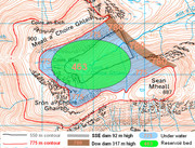
Image also hosted here
The black contour line at 550 metres elevation shows the outline of the SSE proposed reservoir of about 1 square kilometre surface-area and the grey thick line shows the position of the proposed SSE dam which would stand 92 metres tall and would be the tallest dam in Scotland and indeed Britain to date though it seems our dams are several times smaller than the tallest dams elsewhere in the world these days.
Part of the red contour line at 775 metres elevation, where the red line surrounds a blue shaded area, blue representing water, shows the outline of my larger reservoir of about 2 square kilometres surface-area and the thicker brown line shows the position of my proposed dam which would stand 317 metres tall which would be one of the tallest man-made dams in the world, 1475 metres long and about 72 million cubic metres in volume.
Enhanced satellite photograph


Image also hosted here
Cross section of the Dow-dam
The Dow-dam would be more than 3 times higher than the proposed SSE-dam. In this diagram, a horizontal line one third of the way up the Dow-dam indicates the relative height of the SSE dam although it is not aligned with this cross-section.


Image also hosted here
Maps showing the line of cross-section viewed from each side


Image also hosted here


Image also hosted here
Cross section of the Dow-dam reservoir

Cross section along the major diameter of the elliptical excavation of the reservoir bed

Also hosted here
The Upper Reservoir
The green ellipse of major diameter of 1.5 kilometres and minor diameter of 1 kilometre represents an excavated reservoir bed, as flat and as horizontal as practical, at an elevation of 463 metres.
Since an excavated reservoir bed is not, that I can see, part of the SSE plan, except as they need rock for their dam, I will provide some more information about my vision for that now.
The basic idea of excavating a flat or flattish reservoir bed is to increase the volume of the water stored in the reservoir because more water means more energy can be stored.
Capacity of the reservoir, energy stored and power supplied
Excavating around 138 million cubic metres of rock increases the volume of the reservoir so created to about 400 million cubic metres, achieving a theoretical energy storage capacity of more than 600 GigaWatt-Hours and it ought to be possible to excavate enough rock to achieve a practical 600GW.Hrs electrical energy supplied.
Accordingly, I envision it would be appropriate and useful to install the required turbine-pumps to supply up to 12 GigaWatts of electrical power to the grid for up to 50 hours before the energy store would be exhausted.
Excavation details
Depending on the geology and strength of the rock of Coire Glas the walls of the reservoir bed perimeter could be as steep as vertical from the reservoir bed up to the natural elevation of the existing rock surface which would mean, presumably, blasting out rock to create a cliff which at places could be as much as about 290 metres tall.
Near the dam, the reservoir bed perimeter wall would be only 40 metres or less tall. The further from the dam, the higher the wall will be and the more rock needs to be excavated.
A vertical reservoir bed perimeter wall would be ideal to maximise reservoir volume wherever the geology provides a strong stone which can maintain a vertical wall face without collapse, (a stone as strong as solid granite would be nice though Coire Glas looks to be mostly made of a rock called "psammite"). Ideally this would allow about 138 million cubic metres to be excavated to flatten the reservoir bed.
Where the geology only provides a weaker stone then a sloping perimeter wall at a suitable angle of repose for reliable stability would be constructed.
So the reservoir perimeter wall could be as sloped as shallow as 45 degrees from the natural elevation at the perimeter of the eclipse sloping down to the reservoir bed at 463 metres elevation in the case of the weakest and most prone to collapse kinds of stone.
Exactly how strong the stone is at each location I guess we'll only find out absolutely for sure if and when engineers start blasting it and testing the revealed rock wall face for strength.
The shape of the perimeter of the excavated reservoir bed is not absolutely critical. So long as it ends up as a stable wall or slope, however it is shaped by the blasting, it will be fine. There is no need to have stone masons chip the perimeter smooth and flat! The ellipse is simply the easiest approximate mathematical shape to describe and to draw. If the end result is not a perfect ellipse, don't worry, it will be fine!
Geology of the Coire Glas site
I have been able to extract this information from the British Geological Survey (BGS) Geology of Britain viewer, from the 1:50 000 scale map.


Click to see larger image
According to this map, the bedrock at the site which would be used to build the dam on top of and to extract rock from to create the tunnels for the underground complex seems to be a rock geologists call "psammite" which I understand to mean here "a metamorphic rock whose protolith was a sandstone".
What neither the map nor the "psammite" name is telling us is how fractured the psammite rock there is and therefore how strong and also how impermeable or otherwise to water this rock is likely to prove to be, both of which would be interesting for any engineers building a pumped-storage hydro dam scheme there to know.
What does look fairly obvious to me is that the superficial deposit of what the map calls "hummocky (moundy) glacial deposits - diamicton, sand and gravel" would not be strong enough, nor impermeable enough to build any dam on top of and at least along the line of the dam, this glacial deposit ought to be removed to get down to the bedrock within which to establish the foundations of the dam, although I would think that this glacial deposit might be made into aggregate to make the concrete for the dam by the sounds of it.
Dam foundations and height of the dam above the bedrock
The top of the Dow-Dam has an elevation of 780 metres by design.


Image also hosted here
The lowest elevation of the current ground surface of Coire Glas along the line of the proposed dam is 463 metres and subtracting 463 from 780 is how the initial value of 317 metres for the nominal height of the dam above the existing surface used in previous diagrams was arrived at.
However, the glacial deposit of as yet unknown thickness is to be removed before building the foundations of the dam within and upon the bedrock.
Although the lowest surface elevation along the line of the dam of the bedrock too is unknown a formula relating the Height of the Dam Above the Bedrock (HDAB) to the Glacial Deposit Depth (GDD) can be easily stated.
HDAB = 317 + GDD
Examples.
If the GDD turns out to be 13 metres then the dam will be 330 metres tall.
If the GDD turns out ot be 83 metres then the dam will be 400 metres tall.


Image also hosted here
I propose that the height of the Dow-Dam be as tall above the bedrock as it needs to be to keep the top of the dam at an elevation of 780 metres no matter how deep the removed glacial deposit layer turns out to be.
My approach may well differ from the SSE's approach. The SSE have said that their dam will be "92 metres" high and they may stick to that without having any goal for the elevation of the top of their dam.
As the diagram indicates, I propose to secure the Dow-Dam to the bedrock by massive piles inserted and secured into shafts which would be drilled into the bedrock.
Reservoir bed drain
The high pressure of water which is deeper than 100 metres has the potential to induce seismic activity or earthquakes in susceptible rock in which a new reservoir has been constructed.
Wikipedia wrote: Wikipedia: Induced seismicity - Causes - Reservoirs.
The mass of water in a reservoir alters the pressure in the rock below and through fissures in the rocks, lubricates the fault, which can trigger earthquakes.
...
Unfortunately, understanding of reservoir induced seismic activity is very limited. However, it has been noted that seismicity appears to occur on dams with heights larger than 100 meters. The extra water pressure created by vast reservoirs is the most accepted explanation for the seismic activity.
Coire Glas/SSE/92 m
Hopefully, reservoir induced seismicity was an issue considered by the SSE when selecting Coire Glas for their hydro dam project.
I am speculating that this issue may be why the SSE have limited their dam to a height and their reservoir to a depth of 92 metres?
I would note however that the pressure in the head race tunnels which supply water from the reservoir to the turbines would be proportional to their depth below the surface of the reservoir and this could be as much as 500 metres deep, so there would seem to be some potential for water to penetrate the bed rock from the high pressure water tunnels and induce seismic activity even in the SSE case.
This is an issue which ought to have been addressed in the many previous pumped-storage hydro scheme projects, most of which seem to have a difference in head of more than 100 metres.
Given that "understanding ... is very limited" according to Wikipedia, though, I do wonder if the reservoir induced seismicity issue has not always been properly addressed in all previous dam and reservoir construction schemes where the great depth of water and susceptible geology ought to make it a relevant concern?
Coire Glas/Dow/317+m
I am proposing measures to counter the reservoir induced seismicity effect in the case that the geology of Coire Glas is susceptible to it and in the general case.
I propose the construction of a large reservoir surface drain to cover the whole reservoir bed and the reservoir sides too to try to stop the penetration of water under high pressure into fractures in the bedrock and so thereby stop this high pressure water from widening and extending bedrock fractures.
To illustrate my "reservoir bed drain" concept, I have drawn a diagram comparing the usual no drain on the left, with my proposed reservoir bed drain and dam drain pipes on the right.

http://scot.tk/forum/media/reservoirbeddrain.jpg

Image also hosted here.
So my idea is that the top layer of the bed drain is as impermeable as practical, using perhaps a layer of reinforced asphalt concrete.
In engineering practice I believe that impermeable reservoir bed layers have used clay or clay with asphalt or even rubberised asphalt mixed with sand.
My basic idea is to construct an impermeable layer and to use whatever material is best for that.
Then working downwards, the permeable bed drain layers are increasingly bigger loose particles, with sand at the 2nd top then beneath that grit, then gravel, then small stones and finally below all those a layer of large stones.
The higher layers support the top impermeable layer which is under high pressure from the reservoir water and the lower permeable layers provide many small channels for any (hopefully tiny amounts of) water which forces its way through the supposedly impermeable top layer to drain down the slope of the reservoir bed to the base of the dam and then out under the dam through drain-pipes built into the base of the dam.
The bottom layer of the bed drain is another impermeable layer to try to make doubly sure that the relatively low pressure water that gets into the bed drain will find its way out through the dam drain pipes by following the course of the drain.
These kinds of layers of different sized loose particles have previously been used to make simple narrow drains and impermeable layers have been added to reservoir beds before now but whether professional dam engineers have ever covered the entire reservoir bed and sides with one large drain I don't know. If not, this could be named the "Dow drain" solution to reservoir induced seismicity!
Why not add a simple impermeable layer to the reservoir bed?
I think the additional complexity and expense of a bed drain (and drains for the sides too) is better than simply adding an impermeable layer.
Consider the fault condition of the two possible solutions.
If a simple impermeable layer fails, if it cracks or ruptures or disintegrates under the pressure changes, how would anyone know? It may look fine but be leaking high pressure water into the bedrock and inducing seismicity which OK the engineers would notice any earthquakes but so would everyone else, the earthquakes could cause damage or loss of life and it could lead to a loss of confidence in the project and in the engineers who built it. They could go to jail!
If the top impermeable layer of the bed drain fails then there would be some water pouring out of the drainpipes through the base of the dam when at most it should only be a tiny trickle of water. So the engineers would know there was a problem with the bed drain and they'd know to drain the reservoir and fix or replace the top supposedly "impermeable" layer, fix the bed drain so that it operated as it should.
So failure with the bed drain is noticed right away and it is not a catastrophic failure. Whereas failure with the simple impermeable layer may not be noticed until a catastrophic earthquake happens.
So this is why I think the bed drain is worth the extra complexity and expense. It is a more fault tolerant engineering solution.
Loch Lochy and vicinity water flow control works
Here is an annotated satellite photograph of the land south from Coire Glas showing Loch Lochy, Loch Arkaig, the isthmus between the lochs, Mucomir where Loch Lochy empties into the River Spean before it flows on as the River Lochy, the Caledonian Canal and Fort William where the river flows into a sea loch.


Click to see larger image
New waterway
Loch Lochy is separated from a neighbouring loch, Loch Arkaig, by a 2 km wide isthmus, which I have identified on this map as "the Achnacarry Bunarkaig isthmus", after the local place names.
It ought to be quite straight forward to build a canal or culvert, to connect those two lochs. The idea is that the new waterway would be wide and deep enough, enough of a cross section area under water, perhaps hundreds of square metres, so as to allow free flow from one loch to the other, so as to equalise the surface elevations of the two lochs, so as to increase the effective surface area of Loch Lochy so as to decrease the depth changes to Loch Lochy when water flows in from the Coire Glas reservoir when it discharges water when supplying power.
Now, Loch Arkaig has a natural surface elevation of 43 metres and this would be lowered to that of Loch Lochy. The surface area of Loch Arkaig is given by wikipedia as 16 km^2 also, (though it looks to me somewhat smaller than Loch Lochy). In addition, partially draining Loch Arkaig to bring its level down to that of Loch Lochy will also reduce its surface area.
If say, the additional surface area of Loch Arkaig is about 10 km^2 added to Loch Lochy's 16 km^2 this would give an effective surface area of 26 km^2 and reduce the potential depth variation to
Potential depth variation of Loch Lochy + Loch Arkaig = 400 000 000 m^3 / 26 000 000 m^2 = 15.3 metres.
Without equalising the loch levels, the depth changes to Loch Lochy that would require to be managed may be potentially more like 25 metres than 15 metres. So the new waterway is an important part of the new water flow control works that Coire Glas/Dow requires to be constructed.
Additional Loch Lochy water level control measures
When the Coire Glas reservoir is full, then the water level of Loch Lochy should be prevented, by new water works - drains, dams, flood barriers etc. - from rising due to rainfall and natural flow into the loch above a safe level which allows for the reservoir to empty into the loch without overflowing and flooding.
The safe "upper-reservoir-full" loch level will likely turn out to be around about 15 metres below the maximum loch level.
The next diagram showing the new loch drain and the reservoir pump inlets indicates how this might be achieved.


Click to see larger image
The drain from Loch Lochy to the sea which goes underground from the 14 m elevation level in the loch would need capacity for the usual outflow from Loch Lochy which currently goes through the Mucomir hydroelectric station.
I have estimated the flow through Mucomir from its maximum power of 2MegaWatts and its head of 7m as somewhere near 0.2 Mega-cubic-metres-per-hour and compared that value using a spreadsheet I have written to predict the capacity of water flow through different sizes of drains using the empirical Manning formula and this is also useful for determining the appropriate size of the new water channel between the lochs.
Ease my quantity
To construct Coire Glas/Dow/600GW.Hrs/12GW may cost of the order of around £20 billion, but that would be my order of magnitude educated guess more than a professional cost estimate.
In other words, I'm only really confident at this early "vision" stage that the cost would be closer to £20 billion than it would be to £2 billion or to £200 billion but I'm not claiming to be able to quote an accurate cost estimate at this stage.
I have not itemised my costs - how much for land, how much for labour, how much for trucks, how much for diggers, how much for cement, how much to install the generators etc. and the SSE have not published itemised costs for theirs either so I can't calculate my costs in a proportion to the SSE's costs.
Although my version offers 600 GigaWatt-Hours energy and 12 GigaWatts power (or 20 times the capacity and performance) some of the items in my version would cost more than "in proportion", in other words more than 20 times the SSE's cost.
For example, the cost of my dam will be more like 27 times the cost of the SSE's dam. (3.44 times higher and thicker and 2.27 times longer).
For example, the cost of excavating 400 million tonnes of rock from the reservoir bed to increase the capacity of the reservoir to hold water (and energy) in my version won't be in proportion to the SSE costs for excavating their reservoir bed because, as far as I know, they don't plan to excavate their reservoir bed, except for rock for the dam.
On the other hand, my land costs are about the same as the SSE's - much less than in proportion. I may well need to use more land to dispose of the additional excavated rock spoil but perhaps when that additional land has been landscaped over it could be resold?
So it depends how much the land is as a proportion of the SSE's costs. If land is a small part of their costs, if 20 similar sites to build on are just as cheap and easy to buy then my costs will be much more than proportional, since saving land won't save much money.
If land is scarce and valuable and the cost to purchase suitable land with a good chance to get permission to build on it is a significant proportion of the SSE's or anyone's costs to build 20 of their size of hydro dam schemes then my costs may be better than proportional. Sometimes securing suitable land for development can be very problematic, very expensive. Sometimes people won't sell their land. Sometimes the authorities won't agree that the land can be used in this way.
The SSE say that suitable sites for such pumped storage schemes are rare indeed, so land costs may be very significant and my scheme good value for money.
If indeed the cost of my scheme is somewhere around £20 billion it is likely to cost far more than the SSE or any electrical power supply company looking to their annual profits for the next few years could possibly afford.
Something like £20 billion I expect could only be found as a national public infrastructure project, spending government money, like the building of a large bridge or motorway would be.
A £20 billion government project would require Treasury approval, at least while Scotland is ruled as part of the UK.
I have suggested funding my much larger hydro dam scheme by re-allocating of some of the Bank of England's "Quantitative Easing" funds which amount to some £300 billion of new money printed with not much to show for it.
Any Questions?
OK, well I guess that's the vision part over. The rest is fairly straight-forward engineering I hope. Oh, and there is always getting the permission and the funding to build it of course which is never easy for anything this big.
OK, well if anyone has any questions or points to make about my vision or can say why they think the SSE plan is better than mine, or if you don't see why we need any pumped storage hydroelectric scheme at Coire Glas, whatever your point of view, if you have something to add in reply, please do.
_________________
Peter Dow,